SLIDE SHOW

  • ElexIdea.Blogspot.Com

    This Blog is Designed Specially for Help and Communicate those Students Who Deserve to Discover Something New !!!

  • Mobile Phone & Computer Stuff

    Mobile Phones section is designed to Post Some cool softwares, Games and as Well as Computer Section is also added to Post More stuff about Computer, Windows, Mac, Linux, etc...

  • Electronics Circuit and Projects

    Electronics Projects and Circuit is the Core of ElexIdea Blog, Here Electronics engineering students can easily Find about latest Projects and Circuits as Well as Component Detail and Their Data Sheet.

  • Movies Gossip, Latest Songs & World News

    Movies and Latest Songs, Here You Can Find Latest Leak Songs First on Web as Well Link of Latest HD movies...

Showing posts with label Testing of Components. Show all posts

THERMOCOUPLES: THE OPERATING PRINCIPLE

A thermocouple is a device made by two different wires joined at one end, called junction end or measuring end. The two wires are called thermoelements or legs of the thermocouple: the two thermoelements are distinguished as positive and negative ones. The other end of the thermocouple is called tail end or reference end. The junction end is immersed in the environment whose temperature T2 has to be measured, which can be for instance the temperature of a furnace at about 500°C, while the tail end is held at a different temperature T1, e.g. at ambient temperature.
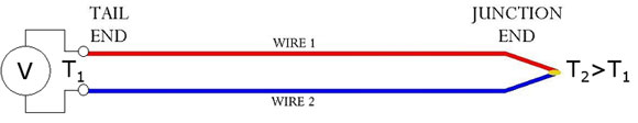
                                                                  Figure 1.

Because of the temperature difference between junction end and tail end a voltage difference can be measured between the two thermoelements at the tail end: so the thermocouple is a temperature-voltage transducer.


Testing a UJT


UJT (Uni junction transistor) can be easily tested by using a digital multimeter.The three steps for testing the health of a UJT are as follows.

1. Measuring the resistance between B1 and B2 terminals.

        Set your digital multimeter in resistance mode.Connect the positive lead of multimeter to the B1 terminal and negative lead to the B2 terminal.The multimeter will show a high resistance ( around 4 to 10K ). Now connect the positive lead to B2 terminal and negative lead to B1 terminal.Again the multimeter will show a high resistance (around 4 to 10K ).Also both the readings will be almost same.

measuring-resistance-between-b1-and-b2


How to test a triac.


Testing triac using a multimeter.


     A multimeter can be used to test the health of a triac. First put the multimeter selector switch in a high resistance mode (say 100K), then connect the positive lead of multimeter to the MT1 terminal of triac and negative lead to the MT2 terminal of triac (there is no problem if you reverse the connection).The multimeter will show a high resistance reading (open circuit).Now put the selector switch to a low resistance mode, connect the MT1 and gate to positive lead and MT2 to negative lead. The multimeter will now show a low resistance reading (indicating the switch ON).If the above tests are positive then we can assume that the triac is healthy. Anyway this test is not applicable triacs that require high gate voltage and current for triggering.


How to test an SCR

SCR internal construction 
Testing SCR using a multimeter.

          A multimeter can be used to test SCRs quite effectively. The first procedure is to check the diode action between the gate and cathode terminals of the SCR. This test is just like what you have done in the case of testing a silicon diode (see testing a silicon diode).

         Now put the multimeter selector switch in a high resistance position. Connect the positive lead of multimeter to the anode of SCR and negative lead to the cathode. The multimeter will show an open circuit. Now reverse the connections and the multimeter will again show an open circuit.


How to test a Diode

Diodes are one of the components that can be tested very easily.Ordinary diodes as wells as Zener diodes can be checked by using a multimeter. While testing a diode the forward conducting mode and reverse blocking mode has to be tested separately. 


single_fire_tach_adapter_diode


Testing ordinary diode using a digital multimeter.
 
      To check an ordinary silicon diode using a digital multimeter, put the multimeter selector switch in the diode check mode. Connect the positive lead of multimeter to the anode and negative lead to cathode of the diode. If multimeter displays a voltage between 0.6 to 0.7, we can assume that the diode is healthy. This is the test for checking the forward conduction mode of diode. The displayed value is actually the potential barrier of the silicon diode and its value ranges from 0.6 to 0.7 volts depending on the temperature.

      Now connect the positive lead of multimeter to the cathode and negative lead to the anode. If the multimeter shows an infinite reading (over range), we can assume that the diode is healthy. This is the test for checking the reverse blocking mode of the diode.


ShareThis

Related Posts Plugin for WordPress, Blogger...
 
ELEX IDEA BLOG © 2012 | Powered by Blogger