Hello,
Friends I am bask with my New Tremendous Circuit which Control your appliances using you TV or DVD remote. Actually I have already Posted a Circuit which have also same funcation as it Works. But This Time its too fast responsive then older one.Actually We are using a Decade counter IC CD4017 which is Very popular for counting purpose. Its a simple and Fast IC we Compare to Last circuit which was based on bistable multivibrator . But this time its Turn to Decade Counter.
Download Project PDF {DOWNLOAD}
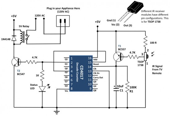
Circuit Diagram is Shown Below :
Circuit Construction
The original circuit diagram for this project was published in the May 2005 issue of the Electronics For You magazine. The circuit diagram below is mostly the same. It uses a TSOP1738 IR receiver module at the input side to receive the 38 KHz frequency IR pulses from the remote control. Under normal condition, the output pin of the IR module is at logic High, which means the transistor T1 (BC557 PNP) is cut-off and its collector terminal is at logic Low. The collector of T1 drives the clock line of the CD4017 decade counter.
Now lets see what happens when somebody faces a TV or DVD remote towards the TSOP1738 and presses any key on it. The TSOP 1738 module receives the train of 38 KHz IR pulses from the remote, that makes its output to oscillate too. These pulses are inverted at the collector of T1, which finally go to the clock input of the decade counter. The arriving pulses could increment the CD4017 counter at the same rate (38 KHz), but because of the presence of the RC filter circuit (R1 = 100K, C1 = 10 uF) between the collector and the ground, the train of pulses appear as a single pulse to the counter. Thus, on each key pressing, the CD4017 counter advances only by a single count. When the user releases the key, the C1 capacitor discharges through the R1 resistor, and the clock line is back to zero. So every time the user presses and releases a key on the remote, the CD4017 counter receives a single pulse at its clock input.
Initially, when the circuit is just powered on, the Q0 output of the CD4017 decade counter goes high. The counter increments for each low-to-high going pulse arriving at its CLK pin (14). When the first pulse arrives, Q0 goes Low and Q1 is turned High. This activates the relay and the AC appliance connected to it is turned on. The status LED connected to Q1 also glows to indicate the appliance is switched on. When the user presses a key again, the second pulse arriving at the CLK line increments the counter by 1. This makes Q1 back to Low (which means the relay is deactivated and the appliance is turned off) and Q2 is pulled High. Since Q2 is wired to the Reset input, the second key press actually brings the CD4017 IC back to the power-on-reset conditions with Q0 High. Thus, it basically operates as an ON/OFF toggle switch controlled with any key of an infrared remote.
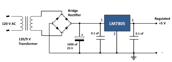
The power supply for the circuit can be derived from the mains AC itself using a step down transformer and a bridge-rectifier circuit. For +5V power supply, the LM7805 regulator IC can be used as shown below.
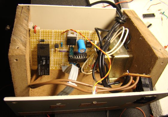
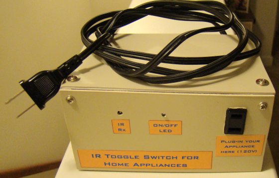
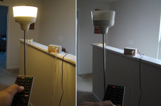
I have enclosed the circuit board with the power supply inside a wooden box as shown in the pictures below. The electrical appliance to be controlled can be powered from the AC outlet at the front side.


0 comments:
Post a Comment
You Like the article, Then Please Leave a Comment here !!!